Electrolytic capacitors (=caps in this text) are parts that often cause problems. So worth the troubles to check them while doing a restoration. The general opinion is replacing all caps. Often not a bad idea but also a bit over the top. Elco’s have not always been problem parts. I have tested many old Spraques (60’s 70’s) for instance that measured still better as the average modern replacements. There are still very good caps in production, made by brands like Panasonic or Rubicon. To bad most modern consumer products only contain the cheapest and lest reliable capacitor brands.
So what to do ? Simple, test the caps. You do not need expensive equipment (but it makes the job more easy) But what to test ? There are a few ways a cap can fail. So I will start with some background information.
Failures:
A cap blocks DC. That is, an ideal cap should do that. To bad ideal caps are very rare. A cap is a resistance for AC. We call that the reactance. A reactance does not dissipate power. That is nice but a cap also has real resistance. A series resistance known as ESR. Together they form an impedance. These 2 things combined can cause problems that lead to a bad cap. The current through the ESR can screw up the working of a circuit and the dissipation can kill the cap. This can end in a shorted cap. The cap heats up, electrolyte vapors, the oxidelayer gets more and more damaged what causes more leakage and more heat until it pops open and spit out its guts.
There are more failures. It can also loose capacitance and end as an open cap with a few nF capacitance.
Beside capacitance a cap has specs for the a maximum voltage and the maximum temperature. These are most times printed on the cap. The temp is simple 85 or 105 degrees Celsius. The voltage can be as low as a few volt upto over 400V. In the datasheet you can find more specs. One important one is the number of hours it should work. Another is the Dissipation Factor at a certain frequency. Often 100/120 or 1000 Hz.
A misunderstanding is the ESR. A lot of people think that this is the resistance at 100kHz. To bad this is not the case. They state the impedance at 100kHz. ESR is stated and calculated from the DF at 100/120 Hz or 1000Hz.
ESR is a combination of a whole bunch of resistances. Things like copper loss, dielectric loss, skin loss. It also has selfinductance (ESL).
Capacitance can be measured with an LCR meter. ESR too or with the use of an ESR meter (or with a scope and a squarewave) More about ESR or DIY ESR meter
Another failure mode is electrode rupture and dielectric absorption. But those failures are rather rare. That leaves us with the DC leakage.
But now you want to know how to find some defects. The first way is easy. Just look at them. Are they bulched, popped open, or deformed they are really dead. No testing needed. Also clean the pcb, the spilled stuff can and will damage your pcb.
The second way is measuring the temperature. If they are hot (by them selves, not because some smartypants placed them on a hot location) they are as good as dead. This is often the phase before they pop.
For other test you need measuring techniques. But before I explain that, there is way we can help a cap to stay healthy. To be more precise, help a cap that is not used in years. The isolating and source of the real capacitance is an oxide layer. This layer is formed by a voltage. And it degrades over time if there is no voltage applied to the cap. This can results in leakage and dissipation of current.
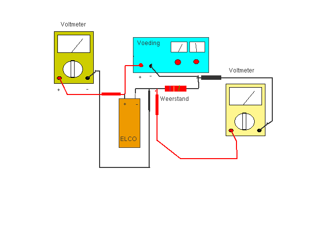
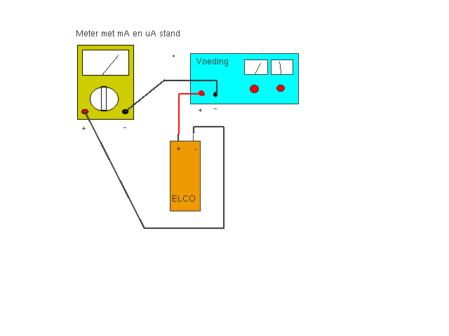
We can help the cap to grow a new layer by applying a voltage and limit the current. This process is named reforming. It can take 30 minutes upto a few hours. We need a DC powersupply and a multimeter to measure the leakage current. A good cap leaks a few uA. A rule of thump for max current (in uA) is 0,01 x voltage x capacitance in uF
A DIY reformer/leakage tester and more about DC leakage and how a cap is build


After testing the leakage and reforming we can measure the capacitance. This can be done in many ways. With a multimeter, a LCR meter, measuring the RC time with a resistor and a psu, Measuring the AC resistance with a multimeter and a function generator. Or do a resonance measurement etc.
But be careful, a high ESR increases the RC time and multimeters use DC to measure the RC time. So a high ESR can be misleading.
