Lead sulfate grows on the plates of a lead-acid battery that is not used for a while and self discharging. Discharging to deep, is very bad for these type of battery. There is soft sulfation and hard sulfation. If the sulfation crystals are still soft it can be cured. If you wait to long (few months) the crystals get hard and this is not curerable.
It is told that if you pulse-load a not to fresh sulfated battery for a long time the sulfate dissolves again (if you are lucky). Most times something like 1A pulses from a few uS up to 50 uS are usable. It takes a few months. The higher the pulse current the faster it should go, but you can not enlarge them endlessly.
An other function of a desulfator is to keep a battery in shape while you store it for a longer time. The battery sees a “good” active load while the total discharge is small because the pulses are short. But if it is for a longer time you should keep it from discharging to much. Every time you total discharge (deep-cycle) a lead-acid battery you lose a part of the capacity. The battery likes to get a 14-16 hours full saturation charge periodically. There are smart chargers that do this. Never leave a battery connected to a charger that has no trickle charge mode. A lot of information about batteries can be found at :
http://batteryuniversity.com/learn/article/lead_based_batteries
Update 2014: The desulfator was connected permanent to a bad 100 Ah car battery for 1.5 years. This battery came from a car and was not used or charged for more as a year. Charging had no effect. Complete dead. See http://www.pa4tim.nl/?p=3550
for the result (the update is at the bottom). After that measurement I wanted to do a load test but I have not done it. I connected a 65mA ledlight to it and that burned only a few hours. But this was a real bad battery.
I think this will not “repair” a bad battery but it probably will prevent a good battery from sulfating while not in use. It is a nice extra function for a car battery charger. It can keep the battery active. For instance connect this for an hour while you disconnect the charger. After an hour disconnect the desulfator and connect the battery. Or let the car voltage be the trigger to switch over by the use of 2 comparators (stop-charge and start-charge) and a relay.
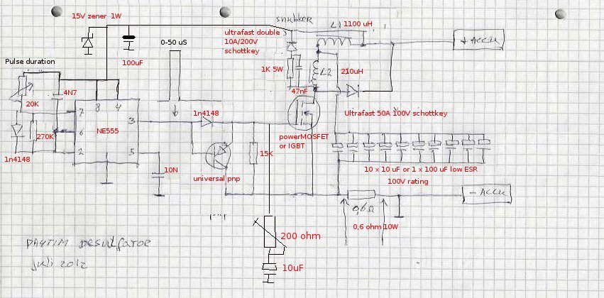
The schematic is the same basis as you find everywhere on the internet. There are a few things important. The two fast diodes must have the right ratings for the current you want. The pulses can reach a voltage of about 50-100V over a very bad battery. And if your inductors are well made the current can easy go up to 20A (for a very short time). I used a carbon composite resistor for the snubber network. They are good for high voltage pulses. I added a 200 ohm potentiometer and a 10uF snubber to the gate. This makes it possible to keep the MOSfet behave and not start to oscillate. A 100 or 50 ohm will do fine too. The thing is nothing more as a boost converter without feedback. When the mosfets conducts a surge current starts to flow from the battery. If the mosfet stops conducting the charged inductor kicks back and makes a high voltage transient over the battery. (and no, it is not a way to charge the battery with is own current.)
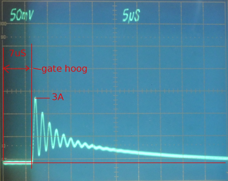
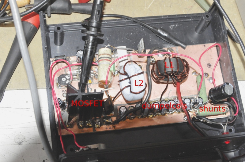
You read a lot about things getting hot and screaming inductors. I tested the inductors on my saturation tester and as soon as they start to saturate they start to make noise. With the coils I made, 7 uS is enough to get a 1A pulse. I can get about 12A before it saturates. From about 3A you hear a soft wistle but as soon as the screaming starts to become loud (and changes pitch) it saturates. In my case the RFC (100mH) is the first to go. Use ferrite with a high AL , so you need only a few turns. The coil heats because a lot of current goes through the resistance of the wire. This is, as said, nothing more then a SMPS with a very low duty cycle. The 210 uH (100 uH will work to but give less current) is the defining factor for the amount of current. The 1100 uH is a RFC (choke) to be sure the 555 and connected charger are decoupled so the pulse has to go through the diode. Not all chargers are happy with these pulses on their output. The value is not critical. If the Xl is 5x higher as the storage coil it will work. The average current is not high so it is also a nice way to keep the battery in shape while you are not using it. The 15V zener is a protector for the 555. If you do not need portable it would be better to feed the 555 part separate.
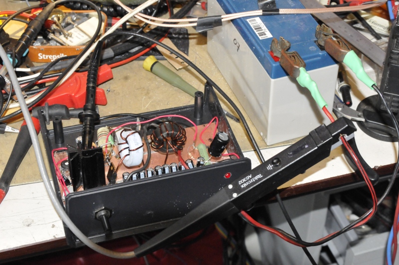
In the photo you see the trace of a Tektronix current probe (1A/div). There is some ringing. This is because the signal from the pulse diode is to close to the coils. In the test I used two wires to the battery and then there was no ringing but I do not care, now I have several pulses for the price of one 😉


