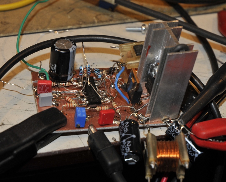
I needed a 12 to 24V boost converter. Most times I use a special smps driver/controller. Once used a 555 but I was in an experimental mood. I found several schematics that all seems to be just copies from each other. It uses two opamps (lm324 or two separate opamps) and a powertransistor, you see two flavours. One opamp as sqaurwave oscillator and one as comparator to make an error signal for the oscillator to regulate the amplitude.
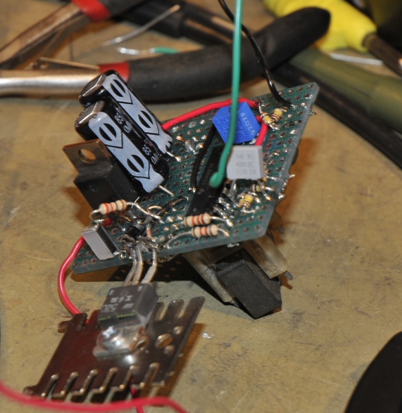
It worked more or less but I could not get it like I want. Killed two BD139 while testing without a heatsinck. Frequency was very low and the BD139 gets very hot. A transistor dissipates the power caused by the voltdrop and if it switches at rather low speed with a rather low rise and fall time the transistor needs to dissipate a lot. So I changed it to a IRF840 MOSFET. They switch much faster with a low Rds on so less dissipation. That was an improvement, same problems but less heat. The main problem was that it was sensitive for paracitic oscillation and voltage jumped from 22V to 90V if I tried to get it over 22,5V to 24V. But everybody builds them so it must be me. Als long as the load was steady it behaved. But veroboard is not the way to go and using a LM324 quad opamp with two floating unused in/outputs is also not good practice and I will not talk about the used coil (that by the way behaved very good in the final version.
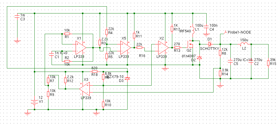
But an opamp is no comparator, you can use it that way but it is like using a minivan as dumptruck. Here both opamps were used as comparators. So I took a LM339, a quad comarator and changed the schematic based on the same idea.
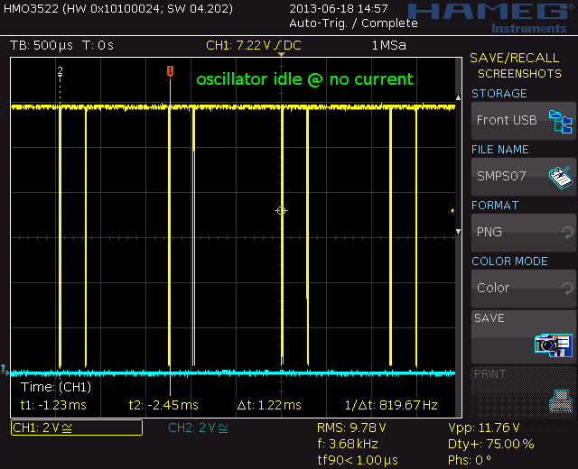
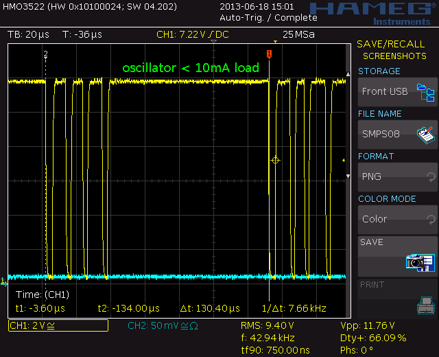
At idle it has a very low dutycycle and frequency. With no load it draws almost no current and the frequency is very low. It a double pulse so frequency is 819 Hz. But this is not as steady as the picture. It goes a bit up and down, there are sometimes longer spaces. The load is now only the voltage divider from the feedback so about 1.5mA. This is a point for improvement by selecting larger value resistors.
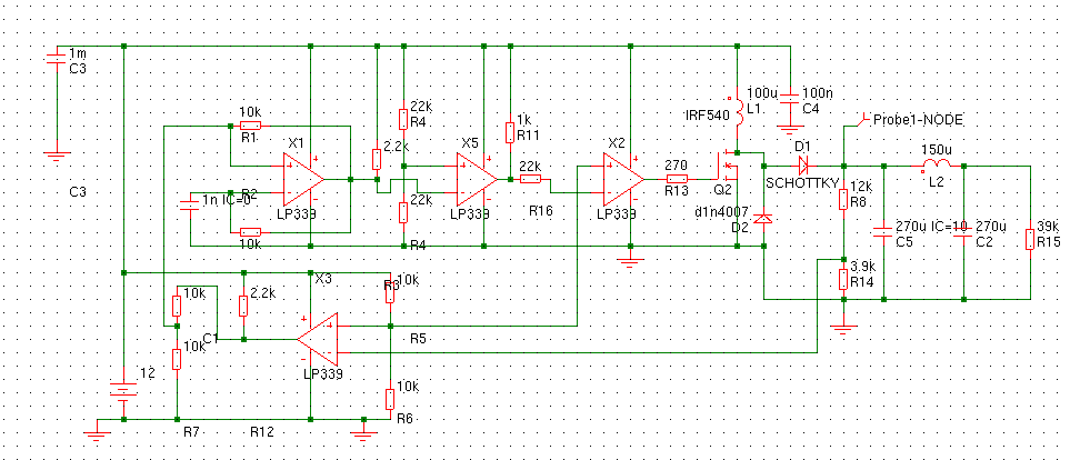
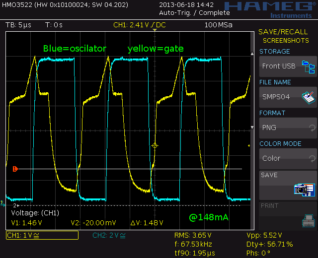
The error amplifier shifts the reference voltage of the oscillator and that changes frequency and dutycycle. The oscillator is measured after the X5, the second comparator. This inverts the signal. X3 inverts it back again. It seems a bit overdone but the oscillator uses feedback. I do not want the gate to influence the oscillator so the second is a buffer and because they invert I needed a second buffer to drive the gate. A 339 is a quad pack so it would be a waist to let it float.
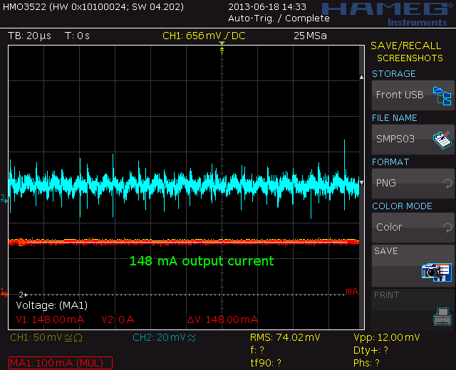
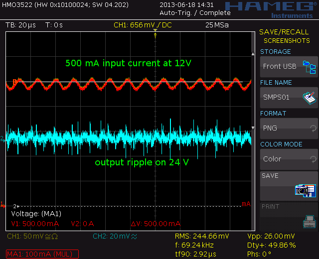
Here it is delivering 148mA into my load. The 24V output then has a 10-20mVtt ripple. And that is unshielded with a very long earthwire on the probe, so an example of ” how not to measure” but not important for my use.
The input current delivered by a Delta 10A PSU at 11,75V is in this case around 500mA. Giving an efficiency around 64%. Not very high but I only need a few mA in this case.
The schematic,.A snubber could maybe improve things but I noticed no difference so I left it out.
The MOSFET is a P55NE06 from my junk box. The schottky diode idem. The coil is 100uH also from my junkbox. I first made some torroids but they kept saturating to soon ( see my saturation tester, http://www.pa4tim.nl/?p=1859 ) These coils, I think from smps filters perform very well. I tested 100, 330, 580uH and 3 mH. It did not matter, all performed the same.
There is one downside. It is stable under different loads but it changes a bit when the input voltage changes. Not much and easy to solve if you use 10V zeners to feed the voltage dividers instead of connecting it to the 12V rail. For me not important because I need only a few mA and feed it with a 7812. I use it to make 27 V to feed a a 7824 that I use to feed a Vref to make 20V Vtune for a signal generator. The schematic is adapted for a zener but my tests are without that.
The gate signal after the gatedriver at 148 mA load. Remember the oscillator is the signal befor the inverter.
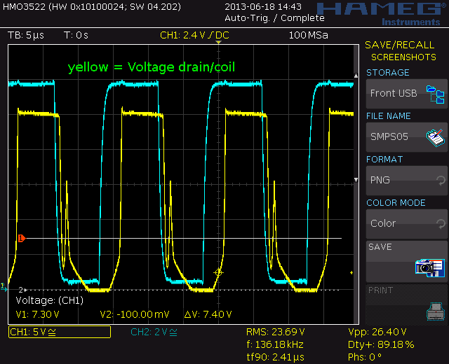
The drain voltage before the diode at 148 mA. The little spike is probably caused by the rectification from the negative spike by the 1n4007. I think a schottkey there could maybe improve things.
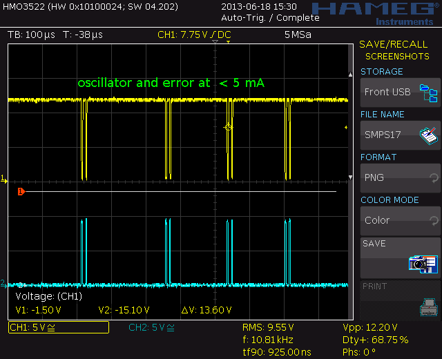
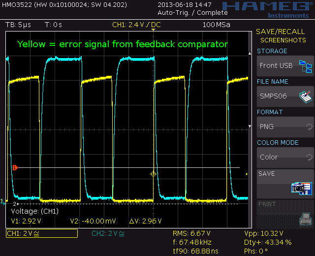
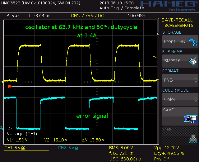
You see the error signal is now shifted compared to the idle picture.
You see the double pulse changes to quad pulses. the frequency is now 7.66 kHz for the pulse group.
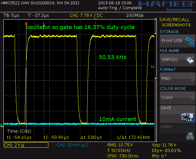
Here it is delivering 10mA. Now you see the dutycycle and frequency regulation becomming more steady. Single pulses at 50 kHz and the gate is pulsed with a 16,4% dutycycle. Lets go to a higher loading.
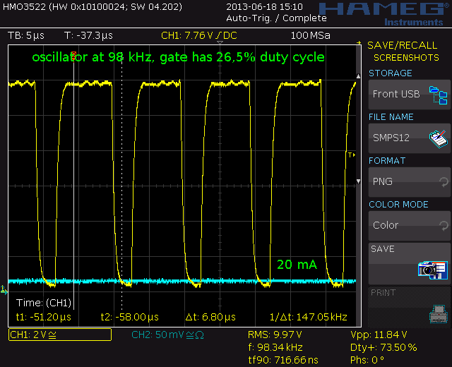
At 20 mA the frequency goes up to 98 kHz and the dutycycle becomes 26,5%
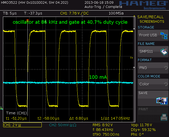
At 100 mA the frequency goes down a bit but dutycycle goes up to 40,7%. Looks like he is reacing his max, or not ? lets see:
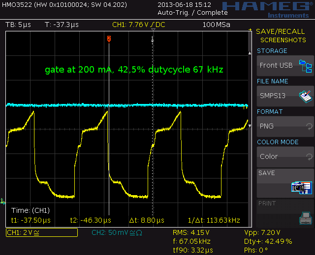
frequency drops to 67 kHz and dutycycle rises to 42,5%. The gate signal is still decent. speeding up the gate by using a smaller resistor and speed up cap could improve efficiency here.
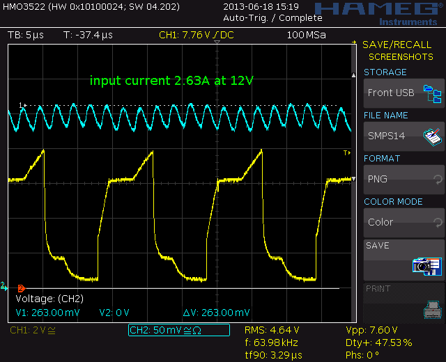
The max current my small load can draw. The Delta has to supply 2,63A at 11,75V. The gate oscillates at 64 kHz and duty cycle is now upto 47,5%. Now look at the output.
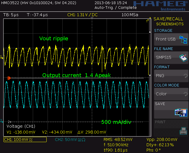
Remember, this smps has only 220 uF as output cap, way to low for 1,4A. With a bigger cap efficiency will improve a lot. If it is able to fill those current rippples the efficiency goes towards 100%.
The ripple current is 510 kHz, (harmonic distortion from diodes, coil, filter etc)
At full power the oscillator is at 63,7 kHz and 49,55%. So the frequency is max. I think a smaller oscillator cap can improve things if you want more power.
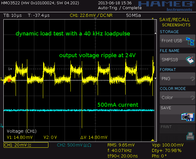
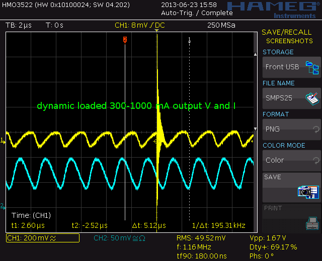
Dynamic test
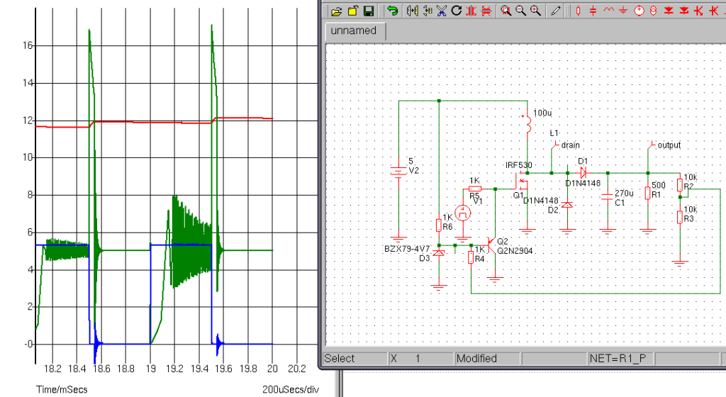
This was the transistor version, here allready with a FET
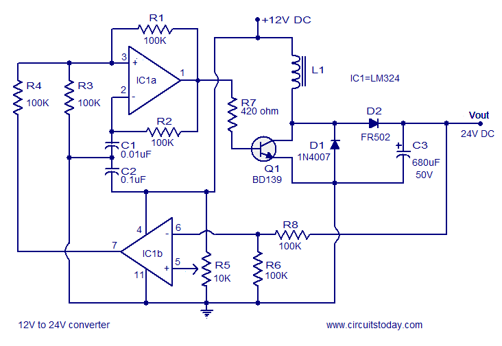
http://www.circuitstoday.com/12v-to-24v-dc-dc-converter This is the schematic from the first version
Source www.circuitstoday.com, but you see it everywhere all 99% the same:
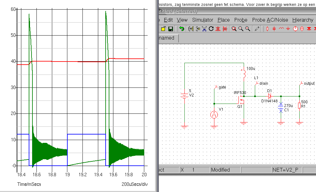
Some Theory:
After replacing the 1nF oscillator capacitot with a 2nF and placing extra caps at the output I was able to increase efficiency upto 80% and draw over 2A from it without problems. The limitting factor is the gate drive. The gate behaves as a large capacitor and must charged and discharged every cycle. The comparator can not deliver enough for full speed. I also removed the gateresistor. This speeded up thing also.
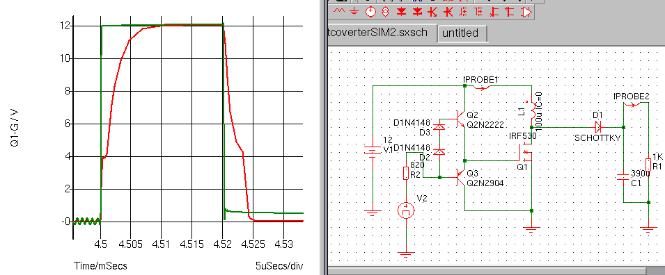
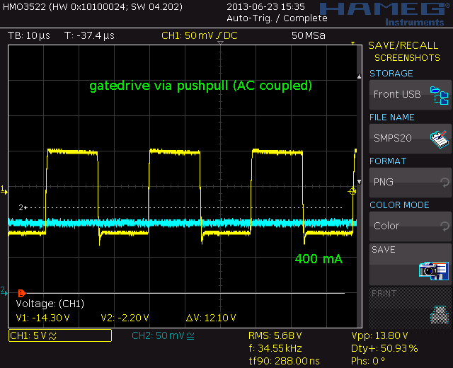
Down here you see a better gatedrive. The green is with the push-pull stage, the red one is with a 14mA gate drive. The pushpull here sources 240 mA pulses and dissipates 1,6W during 200ns (at 20kHz and 20% DC in this simulation)
But sims are not as nice as the real thing. Did I gain something. Yes, effiency went up to 87,8% at 500 mA loading, and I measured 78,2% at 50 mA. I just inserted the transistors between 12V and gnd and the base to the output of the comparators 1 K pull-up. The gate with two ferite beads around the wire to the two emitters.
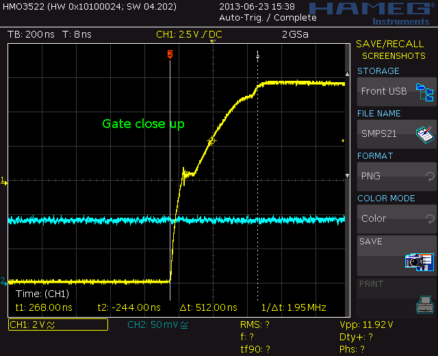
That looks a lot better. Nice fast Tr and Tf. you see a little step:
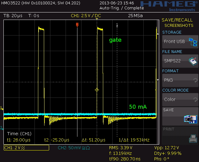
But I need no 400 mA so what about 50 mA:
You see some ringing but that can be the groundwire. By accident I noticed to late I measured AC coupled so Voltage does not go negative (I checked that).
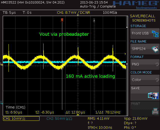
The output ripple is not bad at 24V for a DIY switcher.
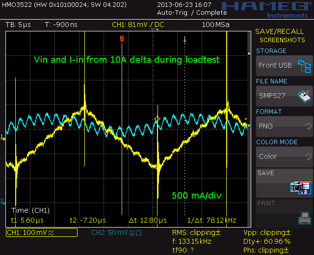
I did some dynamic load testing. Triangle loading. The spike is picked up by the groundwire. But this is the output at 24V. How does the input voltage and current look.
This is the input from my 10A Delta smps labsupply. Yellow is the voltage, blue the current. that is 250mV at 12V and because the DC converter uses the voltage rail as a reference (I have not used the zeners because it will see a stable load and source in my application) So adding a zerner must improve the output.
After a while (somewhere around 10 minutes) testing and loading it with 300-1000 mA, I monitored temperature. My loads heatsinck was 54C, the inductor 34C, the FET 31,9C, the schottky was 44,7C and the transistors (BC307 and BC337) about 30C at 25C roomtemp.
I increased imput capacitance to 15000 uF. The Delta psu driving it realy liked that but no change on the output of the converter. Also tried this cap at the output after the schttky diode but that did allmost nothing. Increased the inductor on the drain to 330 uH but this also did not do much. So it seems rather fool-proof regarding components.
I probed current with a Tek P6042 DC to 75 MHz current probe and the rest with a standard Hameg probe using the much to log groundwire. (only one plot is made with a short groundspring to check noise)

