Video review
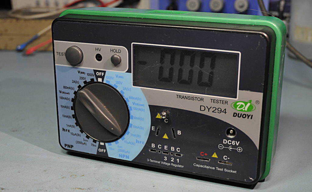
This is a small battery powered transistor tester but it can do more. It can test Vbr, hFE, Vce sat and Iceo. It can test transistors, fets, diodes, leds, zeners, SCR, isolation of MOVs, capacitors, etc
hFE, also called Beta is the DC amplification parameter. It is the ratio between the base current and collector current. There is also hfe, or alfa, the small signal amplification parameter. This is the ratio between the change in base current and the change in collector current. Beta is not a constant. It is not lineair. This tester has 3 different base currents, 10 uA, 1mA and 10mA. Be careful, you can fry a transistor in a flash. As soon as you set the switch on a hFE position it starts measuring. I had rather seen that the pushbutton worked for all functions and not only for HV. Voltage is max 6V, Ic is 2A foor the 1mA and 10mA range and 58uA for the 10uA range.
Measured: Ic: 2A, 2A, 58uA, at 5,98V
Ib: 9,979mA, 0,996mA, 9,92 uA at 5,98V
Vbr, the breakdown voltage is for isolation testing. It generates 1500 or 270Vdc and shows the voltage the component breaks down. You can use this also to test f.i. zeners. The current is low, 544uA for the 1000V range and 712uA for the 200V range.
Measured, Ice: 544 uA at 1622V and 712 uA at 234,8V
Vce(sat) is the saturation voltage, this is the voltdrop over collector and emitter. This must be very low for switching semiconductors so the dissipation is low. Open voltage is 6V. Ic is 2A, 800mA, 100mA or 10mA
Measured, Ice: 1,94A, 0,829A, 100mA, 9,436mA
Ib: 150mA, 76mA, 9,9mA, 0,979mA
Ice, this is a leakage current measurement. It has 1 uA resolution. The voltage is 26V, max current is 2000uA
Measured: 1660uA and 26,25V
DMM DY294
1657uA 1670
2,66uA 0002
1660uA 1665
1188,4uA 1191
518,36uA 511
259,97uA 260
The capacitor connectors are to test the Vbr or Ico of capacitors (not for electrolytics) However, the Ice is usable for low voltage electrolytics.
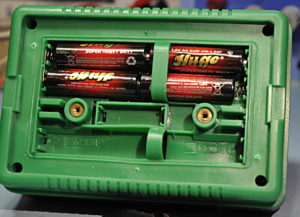
It uses 4 AA batteries or an external 6Vdc powersupply. For the Vce 2A and 800mA you need the external psu.
Soldering was not great to put it mildly.
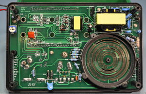
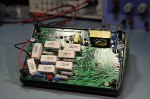
The main pcb. Right top is the HV part
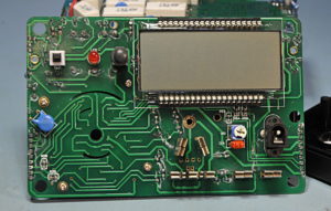
Under the display is a blobbed IC
Piggyback board with the current resistors.
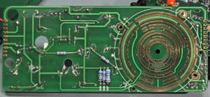
Backside of piggyback board
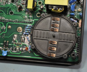
The zero position of the knob
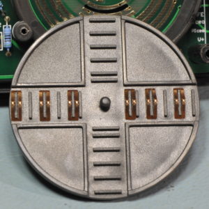
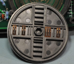
Location of the contacts. Be careful, they lay more or less loose on the disk.

