This during a repair. I did some measurements to show that a DMM is unfit to measure capacitance with the goal to know if it is bad.
New Panasonic low ESR FM, 50V 22 uF
LCR meter: 21,01uF, D=0,025 at 100 Hz
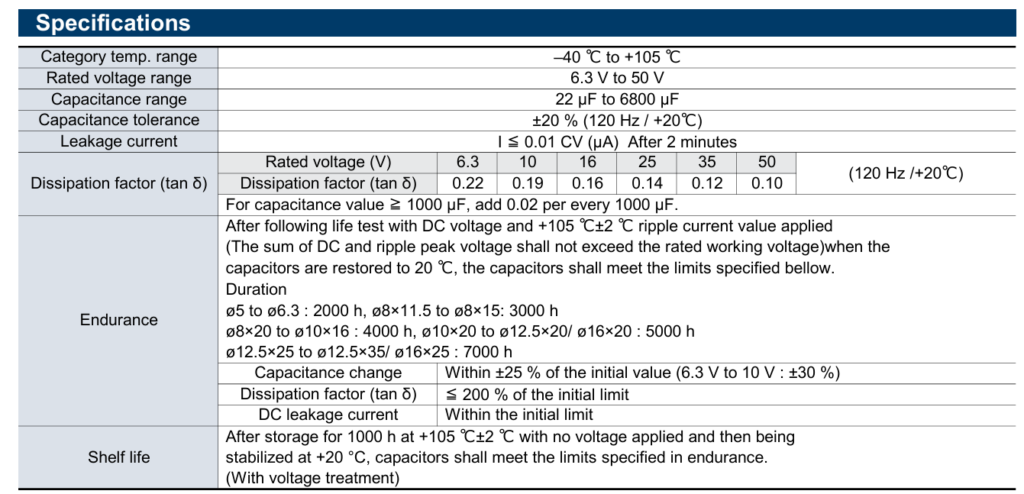
Datasheet: D new max 0,1
At 100 kHz the impedance is |Z|=0,34 ohm, that is: Z=0,33ohm-j0,072, so ESR=0,33 if you measure at 100 kHz.
Worn above: D=200%, so 0,2, capacitance-25%, = 16,5 uF at 100Hz
Z = 7,23 -j72,34. So ESR at 100 Hz is 7,23 ohm
I “made” a cap by mounting a 22uF cap in series with a 34 ohm resister. This emulates a very worn cap that has a D around 0,5, so 2,75x the max new value and 20x the measured new value. More than bad enough to cause problems in a SMPS. If they pop and measure in the nF they were long befor already bad. Popping is the last bread. The high ESR heats up the cap and accelerates wear until it pops.
The DMM works with a DC value and ESR wrongly influences the capacitance value. The higher the ESR, the lower the measured value. That can be as big as 50% or just 15%, it all depends on the meter. My Keysight measured a 47uF cap + 100 ohm as 20 uF while my CEM measured it at 40 uF.
The measurements with a few of my DMMs. Non of them are low budget meters.
The first value without the resistor, the second with the resistor in series
CEM: 21,6 uF and 21,09uF
Peaktech: 21,3 uF and 21,3 uF
Brymen: 22,55 uF and 22,4 uF
Agilent 22,21 uF and 22,16 uF
Fluke 21,7 uF and 21,7 uF
Conclusion, a DMM is totally un-suited to search for bad caps. Unless they are very close to popping, there is a chance ESR is so high and C so low that you measure less than the minimum value (according to the datasheet) in this case 16,5 uF. So if your DMM measures 17 uF, you can have a good or a bad cap and you still do not know if it is good.

Above you see part of the datasheet of this Panasonic FM cap.
The only good ways to measure a cap during repairs are:
– desoldered, using a LCR meter
– Measure the function by measuring the ripple voltage with a scope.
– Measure ESR at 100 Hz or 100 kHz but in that case look up the impedance at 100 kHz, calculate the ESR from that using complex numbers.
If you do not want or can do that ? Life sucks, to bad it has to be done this way . If you are very experienced, always repair stuff with known “most time failures” or have a sound knowledge you can compensate but without the right gear it stays a gamble. You can better do that in a casino and if you win you can buy a scope or a LCR meter  Or you loose everything in both cases …..
Why not in situ ? Often there are capacitors in parallel. For instance you have a 47 uF cap. It is worn down to 30 uF and a high ESR. But the problem is, this rail feeds 15 logic IC’s and every IC has a 1uF cap at its Vcc. They are all parallel to each other and the 47 uF. So you should measure over every one of them 47+15 uF is 62 uF
In this case you measure the worn cap at 30+15=45 uF. So you will think, that is a mighty fine cap if you do not think about those 15 caps in parallel.
